MODEL NO-IM-008
DESCRIPTION
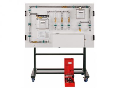
The ”LabTek” Trainer provides a comprehensive experimental introduction to the fundamentals of control engineering using an example of flow control.
A pump delivers water from a storage tank through a piping system. The flow rate is measured by an electromagnetic sensor, which permits further processing of the measured value by outputting a standardized current signal. A Rota meter indicates the flow rate. The controller used is a state-of-the-art digital industrial controller. The actuator in the control loop is a control valve with electric motor operation. A ball valve in the outlet line enables defined disturbance variables to be generated. The controlled variable X and the manipulating variable Y are plotted directly on an integrated 2-channel line recorder. Alternatively, the variables can be tapped as analogue signals at lab jacks on the switch cabinet. This enables external recording equipment, such as an oscilloscope or a flatbed plotter, to be connected.